Rectangular and Square HSS Venting & Drainage Alternatives

What alternatives exist for venting and drainage of rectangular and square Hollow Structural Sections (HSS)?
As with all steel products, hollow structural sections (HSS) must be thoroughly cleaned for the molten zinc to metallurgically bond with the steel. Cleaning solutions should be free to move into hollow sections and completely wet all surfaces of the fabrication and, when removed, no solutions should be trapped inside. In order to facilitate interior and exterior cleaning and coating of HSS products, it is necessary to ensure sufficient venting and drainage.
ASTM A385 discusses the venting and drainage of hollow structures in detail regarding interconnections. However, where end plates are used in combination with HSS, these end-plates must also be designed to facilitate venting and draining. Fully open ends provide minimum obstruction to allow free flow of pretreatment solutions and zinc into and out of the HSS. Since a fully open design is not always possible, incorporating vent/drain holes in the end plates often provides the solution.
For square hollow structural sections (SHS) or rectangular hollow structural sections (RHS) containing end plates, recommendations for venting and drainage are outlined in ASTM A385 (Paragraph 12.4). Specific examples are provided for box sections with end plates (Table 1) and for rectangular tubular products with horizontal end plates (Table 2).
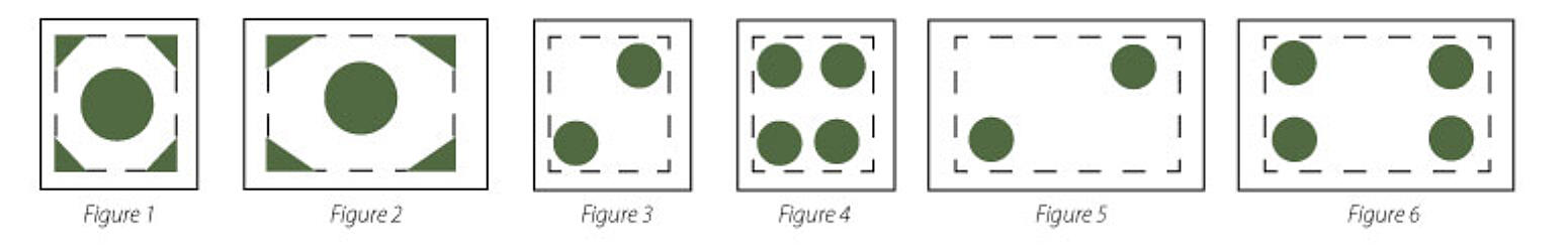
TABLE 1: EXCERPT FROM ASTM A385 FIG. 9 VENTING AND DRAINAGE OF BOX SECTIONS
| Box Size (H+W) | Hole Diameter | Clipped Corner Length |
|---|---|---|
| See Figure 1 for Example | ||
| 48 (122 cm) | 8 (203 mm) | 6 (152 mm) |
| 36 (19 cm) | 6 (152 mm) | 5 (127 mm) |
| 32 (81.3 cm) | 6 (152 mm) | 4 (102 mm) |
| 28 (71 cm) | 6 (152 mm) | 3 (76 mm) |
| 24 (61 cm) | 5 (127 mm) | 3 (76 mm) |
| 20 (50.8 cm) | 4 (102 mm) | 3 (76 mm) |
| 16 (40.6 cm) | 4 (102 mm) | 2 (51 mm) |
| 12 (30.5 cm) | 3 (76 mm) | 2 (51 mm) |
TABLE 2: EXCERPT FROM ASTM A385 FIG. 11 - RECTANGULAR TUBE TRUSS (HORIZONTAL END PLATES)
| Height + Width (H+W) | Area of Hole + Clips/Holes |
|---|---|
| See Figure 2 for Example | |
| H + W ≥ 24 (61 cm) | ≥ 0.25*H*W |
H+ W < 24 (61 cm) & H + W ≥ 16 (41 cm) | ≥ 0.30*H*W |
H + W < 16 (41 cm) & H + W ≥ 8 (20 cm) | ≥ 0.40*H*W |
| H + W < 8 (20 cm) | Fully Open |
However, for vertical members, or fabrications where the minimizing of holes in end plates is preferred, there are alternate designs available which may be suitable for HSS products. ASTM A385 (Paragraph 12.4) outlines a minimum single vent/drain opening to be 25% to 30% of the cross-sectional area, in a corner location. Alternatively, the following venting and drainage hole sizes can be used as a guide for standard SHS (Table 3) and RHS (Table 4) products to provide equivalent venting and drainage using 2 or 4 holes, assuming no internal stiffeners are present. Depending on product length, larger hole sizes may be suggested in the interest of optimizing coating quality.
TABLE 3: ALTERNATIVE VENTING/ DRAINAGE HOLE SIZES FOR SQUARE HOLLOW STURCTURAL SECTIONS OR BOX SECTIONS
| SHS Size | 2 Holes Hole Diameter | 4 Holes Hole Diameter |
|---|---|---|
| See Figure 3 at end for Example | See Figure 4 for Example | |
| 2 x 2" (50 x 50 mm) | 1/2" (13 mm) | 3/8 (10 mm) |
| 3 x 3" (75 x 75 mm) | 3/4" (19 mm) | 1/2" (13 mm) |
| 4 x 4" (100 x 100 mm) | 1" (25 mm) | 3/4" (18 mm) |
| 5 x 5" (125 x 125 mm) | 1-3/8" (35 mm) | 7/8" (22 mm) |
| 6 x 6" (150 x 150 mm) | 1-1/2" (40 mm) | 1-1/4" (30 mm) |
| 8 x 8" (200 x 200 mm) | 2" (50 mm) | 1-3/8" (35 mm) |
| 10 x 10" (250 x 250 mm) | 2-1/2" (65 mm) | 1-3/4" (45 mm) |
| 12 x 12" (300 x 300 mm) | 3" (75 mm) | 2-1/4" (55 mm) |
| 14 x 14" (350 x 350 mm) | 3-1/2" (90 mm) | 2-1/2" (65 mm) |
| 16 x 16" (400 x 400 mm) | 4" (100 mm) | 3" (75 mm) |
TABLE 4: ALTERNATIVE VENTING/DRAINAGE HOLE SIZES FOR RECTANGULAR HOLLOW STRUCTURAL SECTIONS
| RHS Size | 2 Holes Hole Diameter | 4 Holes Hole Diameter |
|---|---|---|
| See Figure 5 at end for Example | See Figure 6 For Example | |
| 3 x 2" (75 x 50 mm) | 5/8" (16 mm) | 1/2" (11 mm) |
| 4 x 2" (100 x 50 mm) | 3/4" (20 mm) | 5/8" (14 mm) |
| 5 x 3" (125 x 75 mm) | 1-1/4" (30 mm) | 3/4" (18 mm) |
| 6 x 2" (150 x 50 mm) | 1-1/4" (30 mm) | 7/8" (20 mm) |
| 6 x 4" (150 x 100 mm) | 1-3/8" (35 mm) | 1" (25 mm) |
| 8 x 4" (200 x 100 mm) | 1-5/8" (40 mm) | 1-1/8" (30 mm) |
| 10 x 6" (250 x 150 mm) | 2-1/4" (55 mm) | 1-1/2" (40 mm) |
| 12 x 8" (300 x 200 mm) | 2-1/2" (65 mm) | 1-3/4" (45 mm) |
| 14 x 10" (350 x 250 mm) | 3-1/8" (80 mm) | 2-1/8" (55 mm) |
| 16 x 8" (400 x 200 mm) | 3-1/8" (80 mm) | 2-3/8" (60 mm) |
| 16 x 12" (400 x 300 mm) | 3-1/2" (90 mm) | 2-1/2" (65 mm) |
Because items being galvanized are immersed in and withdrawn from all cleaning solutions and molten zinc at an angle, vent holes should be located at the highest point and drain holes at the lowest point as mounted during the galvanizing process. It should be noted these alternative venting and drainage designs do not take into consideration the overall design or the lifting orientation that may be required by the galvanizer. Therefore, communication between the specifier and the galvanizer is required if utilizing the above recommendations to determine whether a high-quality coating can still be achieved and to ensure the safety of galvanizing plant personnel is not compromised.
© 2024 American Galvanizers Association. The material provided herein has been developed to provide accurate and authoritative information about after-fabrication hot-dip galvanized steel. This material provides general information only and is not intended as a substitute for competent professional examination and verification as to suitability and applicability. The information provided herein is not intended as a representation or warranty on the part of the AGA. Anyone making use of this information assumes all liability arising from such use.