Pipe Columns, Girders & Poles
This illustration shows the best practice for venting and drainage hole placement and dimensions for pipe columns and girders as well as street light and transmission poles with base-plates and with or without cap-plates.
Location of Openings
- The most desirable fabrication is to have the end completely open, with the same diameter as the section top and bottom.
- This is an equal substitute if the full opening is not allowed.
- This is an equal substitute if the full opening is not allowed.
- This is an equal substitute if the full opening is not allowed.
- This must be used when no holes are allowed in the cap or base-plate: two half-circles 180 degrees apart and at opposite ends of the pole.
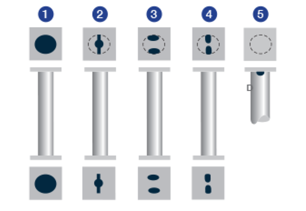
Dimensions
Openings at each end must be at least 30% of the cross-sectional area of the pipe, for pipe 3 (8 cm) and greater and 45% of the cross-sectional area for pipe smaller than 3 (8 cm).
- End completely open
- Slot A = 3/4" (19 mm), Center Hole B = 3 inches (7.6 cm) in diameter
- Half Circle C = 1 3/4" (4.5 cm) radius (examples of sizes for 6" (15 cm) diameter section)
- Oval Opening = 1 3/4" (4.5 cm) radius
- Half Circle D = 5/8" (1.9 cm) radius